SNi50 model
In order to ensure service continuity in an industrial setting, the SNi50 firewall is equipped with two pairs of bypass hardware, which when enabled, enables network traffic to pass through in the event of a power outage or appliance breakdown.
This feature, available from version 4.1 onwards, is disabled by default. If you want to allow bypass to be enabled, high availability must not be configured on the appliance.
The SNi50 multi-function firewall is fanless.
This appliance is equipped with a 48VDC redundant power supply; the 6-pole screw terminal connector provided allows connecting to two independent sources of power.
Connectors and LEDs
|
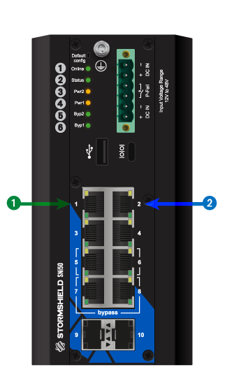
1 OUT interface
2 IN interface
The SNi50 model holds 8 2.5 Gbps Ethernet interfaces and 2 SFP+ sockets for adding 1Gbe/10Gbe Ethernet transceivers. Specifications of Stormshield Network-approved transceivers are set out in the sections Optional Ethernet Transceivers and Fiber Ethernet connectors. |
|
|


Bypass LED
|
Color |
Status |
Status |
|---|---|---|
|
|
Off |
Bypass feature disabled (default status, Security mode). |
|
Green |
On |
Bypass feature configure in Safety mode. The Bypass mechanism will be enabled whenever the appliance breaks down or there is a power outage. |
|
Red |
On |
Bypass mechanism enabled. |
Redundant power supply and P-Fail (Power Failure) relay
REMINDER
Before plugging any equipment into a DC power supply module, read the security rules carefully and follow them.
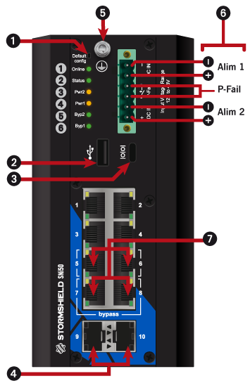
Both electrical power supplies can be connected to the SNi50 to provide a redundant power source. Connect the power supplies according to the diagram shown in Connectors and LEDs
A P-Fail relay makes it possible to detect an abnormal status on a power supply. You can connect this relay to a sound or light alarm, such as a buzzer or a LED, equipped with an independent power supply. To do so, connect the external power supply of the alarm to the third and fourth pins. If both power supplies run at the same time, the alarm will be short-circuited. If either power supply is defective, the alarm will go off. The highest intensity that this relay supports is 1A.