Example 3: NAT rules with a failover between the three outgoing links of the LILLE site
This example illustrates a setup with failover between the three Internet access WAN links of the LILLE site through a router object.
Creating the router object that will be the default route
- Go to Configuration > Objects > Network.
- Click on Add.
- In the column on the left side of the object creation window, select Rrouter.
General properties
- Name the object (e.g., ROUTER-LILLE-WAN-FAILOVER).
Monitoring
- For the Detection method, select ICMP.
- Adjust the Timeout (s) as needed.
- Adjust the Interval (s) as needed.
- Adjust the number of Failures before degradation (3 by default).
SD-WAN SLA (thresholds)
- Select SD-WAN SLA (thresholds).
- Adjust the Latency (ms) as needed.
- Adjust the Jitter (ms) as needed.
- Adjust the Packet loss rate (%) as needed.
- Do not enter an Unavailability rate (%).
Gateways
- In the Gateways used tab, click on Add.
- In the Gateway column, select the object LIL-WAN-1.
- In the Device(s) for testing availability column, select Test the gateway directly.
- In the Backup gateways tab, click on Add.
- In the Gateway column, select the object LIL-WAN-2.
- Repeat steps 17 and 18 to add the object LIL-WAN-3.
- In the Device(s) for testing availability column, select Test the gateway directly.
Advanced properties
- In Advanced properties, select No load balancing for the Load balancing field.
- For Enable backup gateways, select When all gateways cannot be reached.
- Click on Apply then Save.
Setting this router object as the FW-LILLE firewall's gateway
- Go to Configuration > Network > Routing.
- In the Default gateway field, select the router object that was created earlier (ROUTER-LILLE-WAN-FAILOVER in this example).
- Click on Apply then Save.
Creating the filter rule that allows internal networks to access the Internet
- Go to Configuration > Security policy > Filter - NAT, Filtering tab.
- Click on New rule > Single rule.
- Double-click in any column in this rule.
- General menu on the left: switch the Status of the rule to On.
- Action menu, General tab: set the Action to pass.
- Source menu on the left: double-click on the object Any and replace it with the object Network_internals.
- Destination menu on the left: double-click on the object Any and replace it with the object Internet.
- Port/Protocol menu on the left: add to the grid the Destination ports of the various objects corresponding to the ports to be allowed in this filter rule.
- Inspection menu on the left: we recommend leaving the default Inspection level, IPS.
- Click on OK.
- Click on Apply.
Creating address translation (NAT) rules for traffic towards the Internet
- Go to Configuration > Security policy > Filter - NAT, NAT tab.
First LILLE WAN access link
- Click on New rule > Single rule.
- Double-click in any column in this rule.
- General menu on the left: switch the Status of the rule to On.
- Original source menu on the left, Source hosts grid: double-click on the object Any and replace it with the object Network_internals.
- Original destination menu on the left:
- In the General tab, Destination hosts grid: double-click on the object Any and replace it with the object Internet.
- In the Advanced properties tab, Outgoing interface field: select the object corresponding to the first LILLE WAN interface (WAN-1 in the example).
- Translated source menu on the left:
- Translated source host field: select the object corresponding to the first public IP address of the firewall (Firewall_WAN-1 in this example).
- Translated source port field: select the object ephemeral_fw.
- Select Choose random translated source port.
- Click on OK.
Repeat steps 2 to 9 to create the NAT rules corresponding to the two other WAN access links of the LILLE site with the following objects:
Second LILLE WAN access link
| Field | Value |
| Original source - Destination hosts | Network_internals |
| Original destination - Destination hosts | Internet |
| Original destination - Outgoing interface | WAN-2 |
| Translated source - Translated source host | Firewall_WAN-2 |
Third LILLE WAN access
| Field | Value |
| Original source - Destination hosts | Network_internals |
| Original destination - Destination hosts | Internet |
| Original destination - Outgoing interface | WAN-3 |
| Translated source - Translated source host | Firewall_WAN-3 |
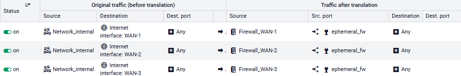
These NAT rules will then look like this: