Settings for firewall FWA2
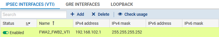
Following the method descibed for firewall FWA1, create a virtual IPsec interface (VTI) on which the IPsec tunnel between firewall 2 on site A (FWA2) and firewall 2 on site B (FWB2) will be based:
- Name: FWA2_FWB2_VTI in the example,
- IP address: 192.168.102.1 in the example,
- Mask: 255.255.255.252 in the example,
Even though the firewall performs routing in the filter policy (Policy Based Routing) in this configuration, a default route or an explicit static route to the remote network needsto be defined.
The first action that the firewall performs is indeed to check that it has a route to the remote site before looking up its filter policy. The absence of a route will result in packets being rejected.
Following the method described for firewall FWA1, create 2 routes that allow transporting return packets to the original firewall using the source MAC address.
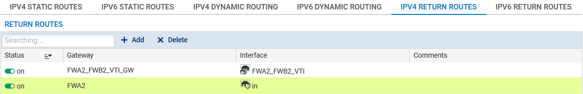
Return route to firewall FWB2
- Gateway: create the network object corresponding to the virtual IPsec interface of firewall 2 on site B (FWA2_FWB2_VTI_GW with the IP address 192.168.102.2 in the example),
- Interface: select the local virtual interface defined for the IPsec tunnel between firewalls 2 on sites A and B (FWA2_FWB2_VTI in the example).
Enable the route by double-clicking in the Status column.
Return route to firewall FWA1
- Gateway: create the network object corresponding to firewall 1 on site A (FWA1 in the example),
NOTE
The MAC address of firewall FWA1 must be declared in this network object.
- Interface: select the interface on firewall FWA2 through which return packets will be transported to firewall FWA1 ("In" in the example).
Enable the route by double-clicking in the Status column.
Following the method described for firewall FWA1, create a filter rule that will send encrypted traffic through the tunnel based on the virtual IPsec interface:
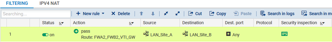
Action column
- Action: set the action to Pass,
- Gateway - router: select the virtual IPsec interface of firewall 2 on site B (object FWA2_FWB2_VTI_GW in the example),
Source column
- Source hosts: select the network at the source of the traffic that needs to be encrypted (LAN_Site_A in the example).
Destination column
- Destination hosts: select or the network object (host, host group, IP address range or network [LAN_Site_B in the example] at the destination of the encrypted traffic.
Dest. port column
- Destination port: select the port(s) corresponding to the protocols that need to be encrypted (Any in the example).
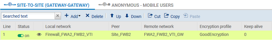
Following the method described for firewall FWA1m create an IPsec VPN policy for the encryption of traffic processed by following FWA2:
- Peer: create an object corresponding to the public IP address of firewall FWB2,
- Local network: select the object corresponding to the local virtual IPsec interface (Firewall_FWA2_FWB2_VTI in the example),
- Remote network: select the object corresponding to the remote virtual IPsec interface (FWA2_FWB2_VTI_GW in the example).