Settings for firewall FWA1
Create the virtual interface on which the IPsec tunnel between firewall 1 on site A (FWA1) and firewall 1 on site B (FWB1) will be based.
In the Configuration > Network>Virtual interfaces menu, select the IPsec interfaces (VTI) tab and click on Add.
Enter the following mandatory fields:
- Name (FWA1_FWB1_VTI in the example),
- IP address (192.168.101.1 in the example),
- Mask (255.255.255.252 in the example).

Even though the firewall performs routing in the filter policy (Policy Based Routing) in this configuration, a default route or an explicit static route to the remote network needsto be defined.
The first action that the firewall performs is indeed to check that it has a route to the remote site before looking up its filter policy. The absence of a route will result in packets being rejected.
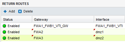
Create 3 routes that allow transporting return packets to the original firewall using the source MAC address:

Return route to firewall FWB1
In the Configuration > Network > Routing menu, in the Return routes tab, click on Add and fill in the mandatory fields:
- Gateway: create (
 icon) the network object corresponding to the virtual IPsec interface of firewall 1 on site B (FWA1_FWB1_VTI_GW with the IP address 192.168.101.2 in the example),
 - Interface: select the local virtual interface defined for the IPsec tunnel between firewalls 1 on sites A and B (FWA1_FWB1_VTI in the example).
Enable the route by double-clicking in the Status column.
Return route to firewall FWA2
- Gateway: create the network object corresponding to firewall 2 on site A (FWA2 in the example),
NOTE
The MAC address of firewall FWA2 must be declared in this network object.
- Interface: select the interface on firewall FWA1 through which return packets will be transported to firewall FWA2 (Dmz1 in the example).
Enable the route by double-clicking in the Status column.
Return route to firewall FWA3
- Gateway: create the network object corresponding to firewall 3 on site A (FWA3 in the example),
NOTE
The MAC address of firewall FWA3 must be declared in this network object.
- Interface: select the interface on firewall FWA1 through which return packets will be transported to firewall FWA3 (Dmz2 in the example).
Enable the route by double-clicking in the Status column.
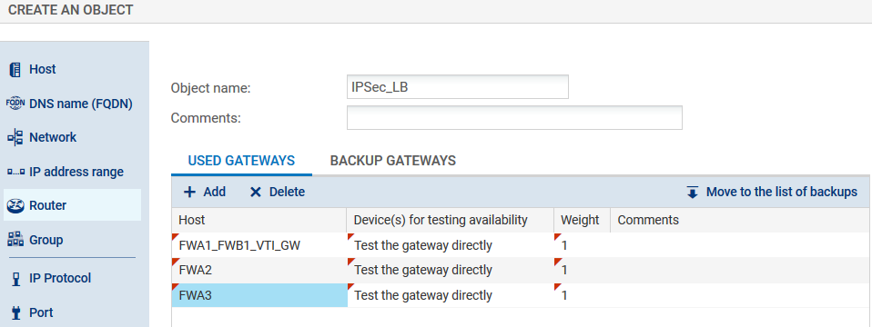
Packets meant to be encrypted in the 3 IPsec tunnels are balanced using a router object made up of firewalls FWA2, FWA3 and FWB1.
- In the Configuration > Objects > Network objects menu, click on Add and choose Router:
- Enter a name for this object (IPsec_LB in the example).
- In the Gateways used tab, click on Add and select the virtual IPsec interface of FWB1 (FWA1_FWB1_VTI_GW). Leave the value Test the gateway directly for the column Device(s) for testing availability. Likewise, leave the value 1 in the Weight column.
- Repeat this operation to add gateways FWA2 and FWA3.

- In the Advanced properties panel, check that the various fields have been entered with the following values:
- Load balancing: By connection (each new connection that needs to be encrypted in an IPsec tunnel will be sent to one of the gateways declared based on round robin scheduling),
- Enable backup gateways: When all gateways cannot be reached,
- Enable all backup gateways when unavailable: unselected
- If no gateways are available: Default route.
- Confirm the creation of the router object by clicking on Create.
In order for traffic to be shared evenly between the 3 firewalls (FWA1, FWA2 and FWA3) and to go through their respective IPsec tunnels, create a filter rule (Configuration > Security policy > Filter and NAT menu) that includes a routing directive based on the router object created earlier.
Status column
Double-click on the Status column to change the status of the rule to On.
Action column
- Action: set the action to Pass,
- Gateway - router: select the router object created for load balancing (IPsec_LB in the example).
Source column
- Source hosts: select the network object (host, host group, IP address range or network [LAN_Site_A in the example] at the source of the traffic that needs to be encrypted.
Destination column
- Destination hosts: select or create the network object (host, host group, IP address range or network [LAN_Site_B in the example] at the destination of the encrypted traffic.
Dest. port column
- Destination port: select the port(s) corresponding to the protocols that need to be encrypted (Any in the example).
Confirm and apply. The filter rule will then look like this:

Create an IPsec VPN policy for the encryption of traffic processed by firewall FWA1 (1/3 of the encrypted traffic, the rest being shared as well among routers FWA2 and FWA3).
- In the Site to site (gateway-gateway) tab in the Configuration > VPN > IPsec VPN menu, click on Add and select Site to site tunnel.
- Create a peer (IKEv1 or IKEv2) with the following characteristics:
- Remote gateway: create an object bearing the public IP address of firewall 1 on site B (FWB1 in the example),
- Name: you can either leave the name suggested by default (Site_FWB1 in the example) or customize it,
- Select the certificate to be presented or indicate a pre-shared key depending on the chosen authentication method (for further detail, please read the relevant online documentation: How to IPsec VPN - Pre-shared key authentication and How to IPsec VPN - Certificate authentication
- In the Local network field, select the object corresponding to the virtual IPsec interface on firewall FWA1 (Firewall_FWA1_FWB1_VTI in the example).
- In the Remote network field, select the object corresponding to the virtual IPsec interface on firewall FWB1 (FWA1_FWB1_VTI_GW in the example).
The IPsec VPN policy on firewall FWA1 will then look like this:

Save (Save button) and apply this policy (Enable this policy button).