Architecture presented
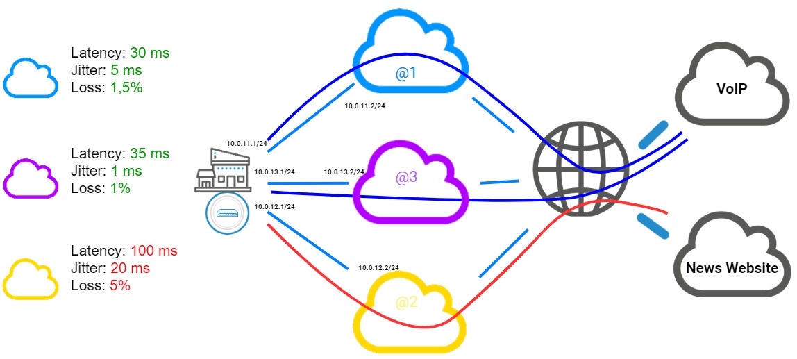
The configuration used in this technical note illustrates the example of an organization that has three remote access links:
- Two links associated with two routers (named Router1 and Router2 in this technical note) from an ISP,
- One link associated with one router (named Router3 in this technical note) from another ISP,
Both links from the first ISP are used as main links, while the one from the second ISP is designated as a backup link.
Load balancing is set on active links.
The SD-WAN configuration described must allow VoIP traffic to transparently go through the network links with the highest performance at any given moment, which web traffic goes through the other link.
The table below shows how links will be chosen based on their respective statuses at a given moment: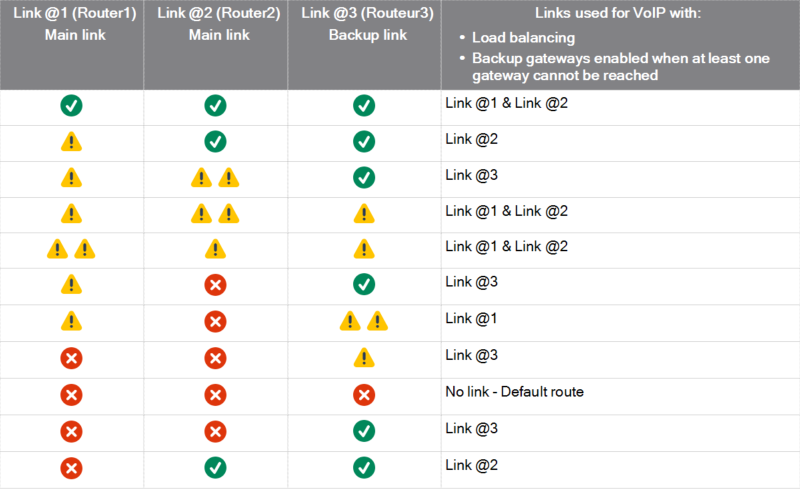
Legend

|
Optimal link | |

|
Degraded link (does not meet SLA thresholds) | |
|
|
Highly degraded link (when several links are degraded : link with the lowest score) | |

|
Link not available |