Architectures presented
Scenario 1: joining two sites that share the same address plan
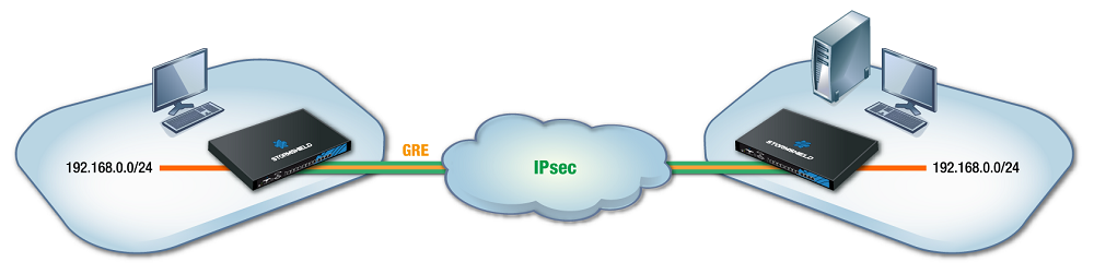
This section shows the scenario in which an organization uses a bridge to link two sites that share the same address plan. Services such as DHCP, for example, and shared network resources will therefore be treated as local services, regardless of which site the user is on. To secure such exchanges, GRE traffic will be encrypted in an IPsec tunnel.
NOTE
The IP addresses assigned to devices on both sites must of course be unique.
Scenario 2: transporting several VLANs through a GRE tunnel without inter-VLAN filtering/routing
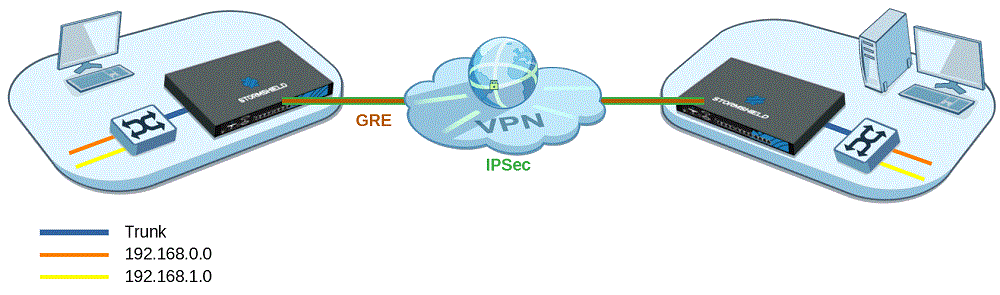
This section shows the scenario in which an organization shares several VLANs between two sites through a GRE tunnel secured by encryption (IPsec).
This configuration allows inter-VLAN communications through the GRE tunnel.
In this architecture, VLANs are not declared on firewalls – no specific operations that rely on VLAN interfaces can therefore be applied, and all VLANs are implicitly allowed to go through the GRE tunnel.
The firewall only knows the IP networks associated with VLANs, and these networks may be specifically filtered, for example.
Level 3 switches located on the LANs of each site route traffic. In this configuration, the link between firewalls and switches is a trunk link, and all VLAN tags are sent back through the tunnel.
We will cover the creation of GRETAP interfaces and the configuration of physical interfaces associated with GRETAP interfaces (advanced settings Keep VLAN IDs and Keep initial routing), as well as the creation of the IPsec tunnel.
- IMPORTANT
If your configuration requires specific filtering to be applied to VLANs before going through the GRE tunnel, refer to Scenario 3.
Do note that this scenario can be applied to architectures that contain more than two firewalls (star configuration), but can never apply to a full mesh topology.
Scenario 3: transporting VLANs through a GRE tunnel with VLAN filtering
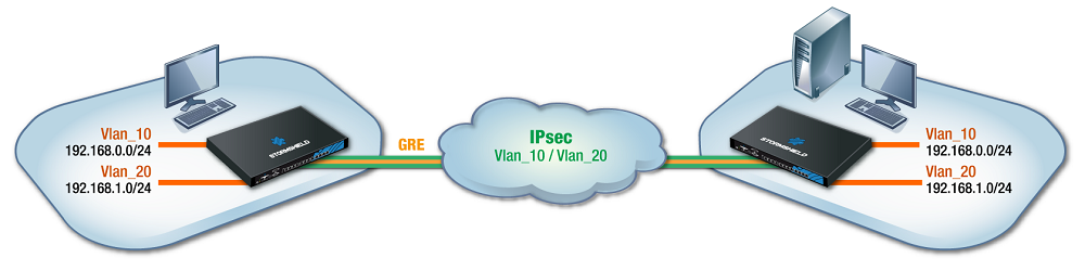
This section shows the scenario in which an organization shares two VLANs between two sites through a GRE tunnel secured by encryption (IPsec).
This architecture does not allow inter-VLAN communications through the GRE tunnel.
It covers the specific configurations of GRETAP interfaces, IPsec tunnels, VLAN settings and their connection to GRETAP interfaces.
Associating a bridge to each VLAN makes it possible to filter VLANs through the tunnel – only VLANs declared on firewalls are allowed to go through the tunnel.
- This configuration generates routing between the VLANs transported through the tunnel and if the machines from both VLANs attempt to communicate with one another through the tunnel, the firewall hosting the GRE tunnel will detect IP spoofing.
If your configuration requires inter-VLAN communication, refer to Scenario 2. - As a bridge is used for each transported VLAN, ensure that the firewall supports the number of bridges planned.
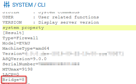
The system property command (Configuration > System > CLI module) makes it possible to identify the number of bridges that the firewall supports: